Solar Pergola Roof Redux: The Plan
Laying 'em flat didn't work, time to get tilted
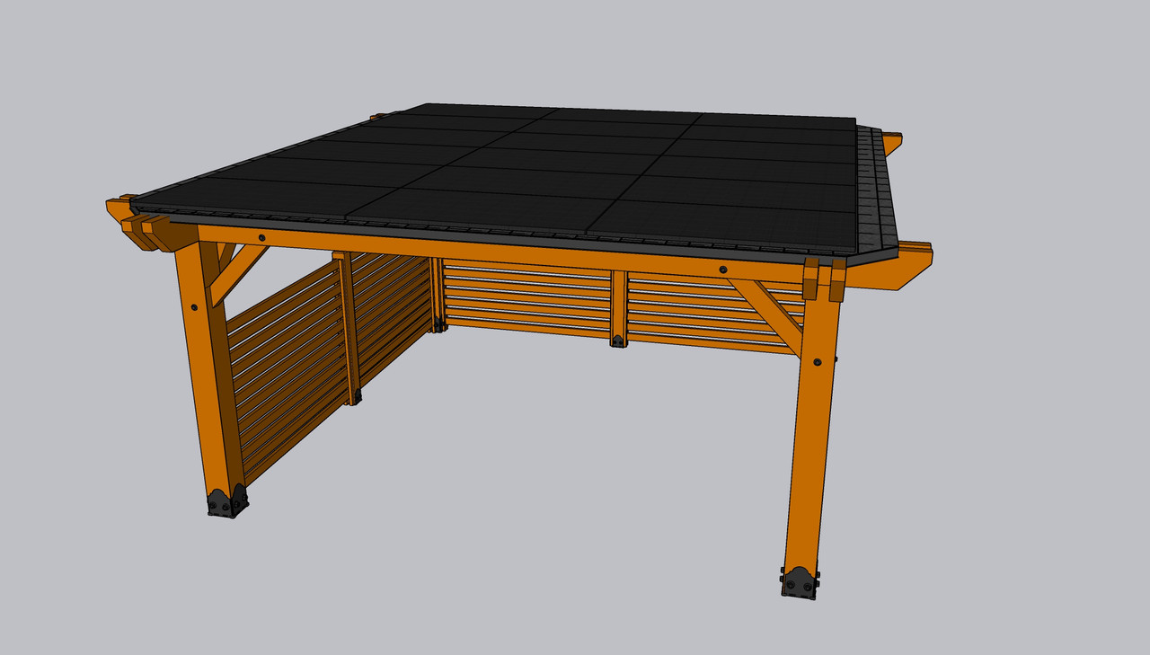
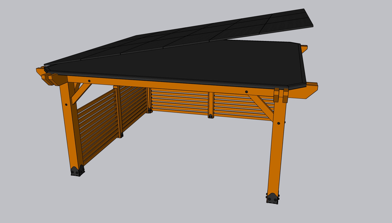
So now that there’s a new roof on my pergola I can move forward with rebuilding the solar array. Sometime last year I came up with the idea of adapting a ground based solar array for use on a flat roof. It took me a few revisions but the final idea that emerged takes all eighteen panels in the same plane and tilts them as one unified array instead of the spaced rows layout that is common to flat roof installations. Under #20/20Hindsight if I had built the pergola footprint a bit larger in one direction that could have yielded sufficient surface area to do spaced tilted rows. Alas, reality has given me a different set of cards to play. With that, let’s once again cue the Ocean’s Eleven theme.
The objective was to create a mounting system that would let me utilize all eighteen existing solar panels but also let me tilt them to allow for better cleaning, water drainage, and snow removal. Since the panels took up the entirety of the roof’s surface area before, the ideal option was to find a way to keep all of the panels in the same plane, and then tilt them as one body.
Like a ground based solar array, the panels would be arranged the same as if they were anchored to a pitched roof. But unlike a ground array I won’t be using a central pole, metal profile beams, or steel pipe as a foundation. I wanted to use steel pipe since that would likely have been the most cost effective and simplest to install, but I couldn’t find a decent anchor plate to use that could be flashed and sealed to prevent leaks. I shopped around over the course of six months researching what solar racking systems I could cobble together to fashion a tilted foundation because, at the very least, it didn’t seem like any manufacturers saw a market for this type of setup. Whether there’s evidence indicating that doing this is risky, especially in snowy climates, I have no idea. So technically I’m taking a risk with how I’m doing this. If ultimately this design fails, at least I’ll have an explanation for why there’s no racking system to pitch a multi-panel array. But knowing this, as one might expect, I’ll be going straight to (what I hope is) overkill.
While there aren’t (as of writing this) any racking systems that will tilt a group of solar panels and play nice with a flat rubber roof, I did find mounts for a single panel that could be safely anchored through EPDM. These were usually sold as a kit that consisted of two short legs anchored via single bolt that had either a fixed or adjustable tilt bracket that would support one side of a solar panel, and then two more legs that usually pivot at the base and support the other side of the solar panel. Using rails to connect these together allows for a row of panels to be uniformly installed.
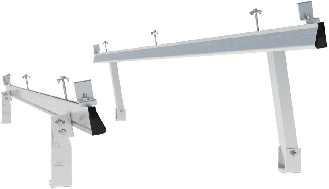 If I were doing spaced rows this is the system I would have used.
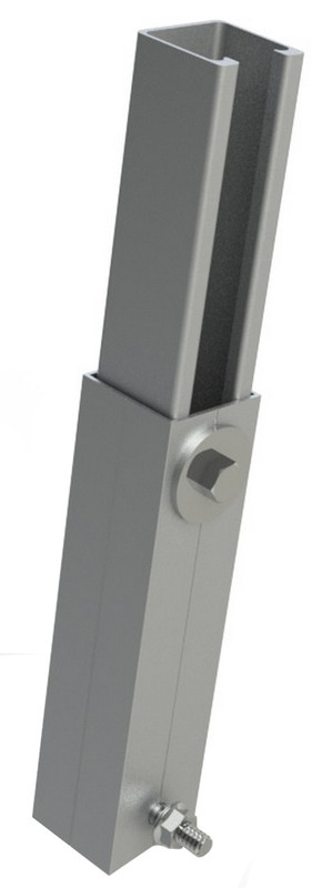
I also came across this style of adjustable leg available in multiple sizes.
This got me thinking about a way to expand on IronRidge’s kit above. Sure I could use the telescoping legs combined with pivoting brackets at the base to get the right height and tilt angle for everything after the first row, but locking it all together was the head scratcher. Furthermore I had to be smart about where the roof anchors would go (this was before I had the new roof installed). I figured I could bolt a set of rails across the individual rows, and that would lock everything into square and prevent panels from slamming into each other. But I still needed to figure out roof anchor placement.
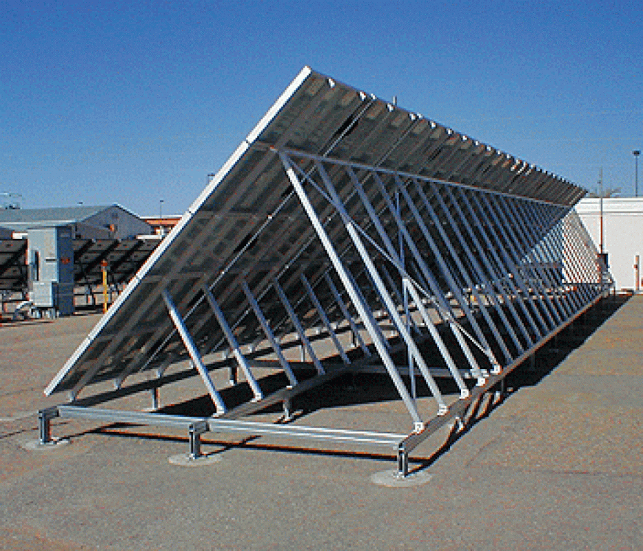
Then I came across this:
My response? Literally this:
This design checked all of the boxes: the panels are tilted as a single body, the entire mounting grid for the panels is locked together, and the structure sits on a base rail system minimizing the number of roof penetrations (there would be at least 200-300 in the photo without those base rails) and maximizing anchor location flexibility. Now that I had a concept, it was back to Sketchup.
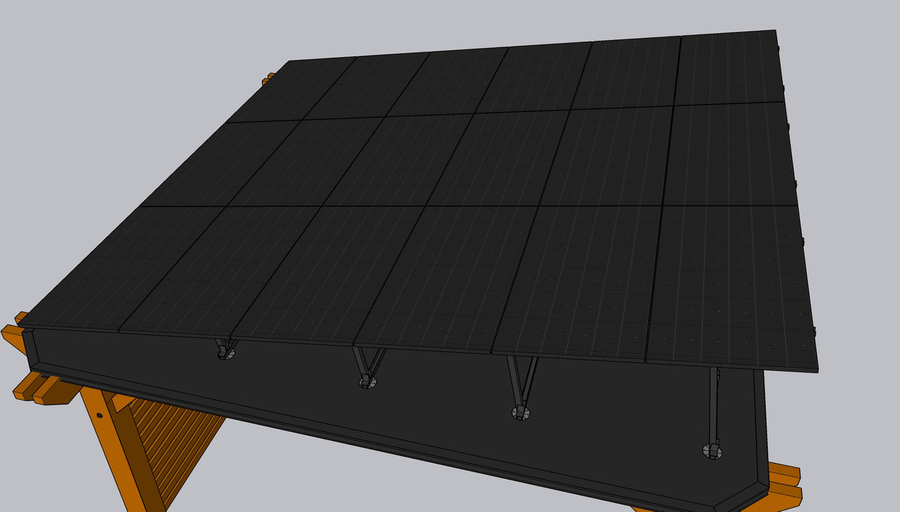
I actually started modeling things in reverse order from how they’re shown below. My panels are a fair bit larger than the ones in the photo I found, and the tilt angle I’m aiming for (10 degrees) is much lower than pictured, plus I wanted to utilize as much of the surface area of the roof as possible in order to provide maximum strength (Crysis fans should be hearing that sound bite from the suit right now). And as mentioned before I also had the roof joist locations to take into account for the anchors.
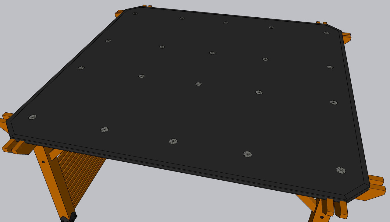
At the very least I needed two outer support rails and a center one. Factoring in the overkill requirement, I added one more rail in between the outer rails and the center. This resulted in the following anchor locations:
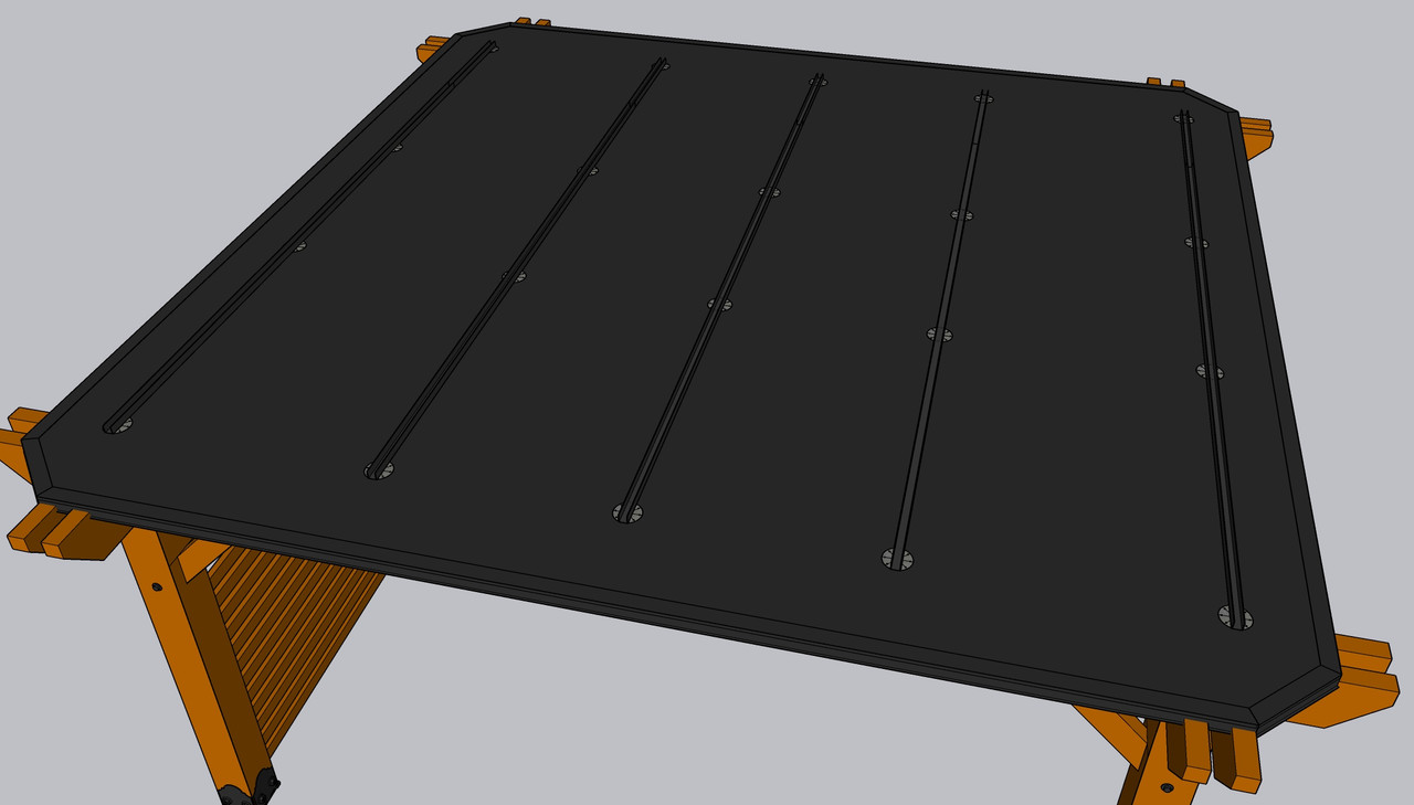
I didn’t feel the need to raise the entire frame off the roof, and the anchor plates have a threaded bolt sticking up, so the plan is to secure the lower frame rails directly to the anchors.
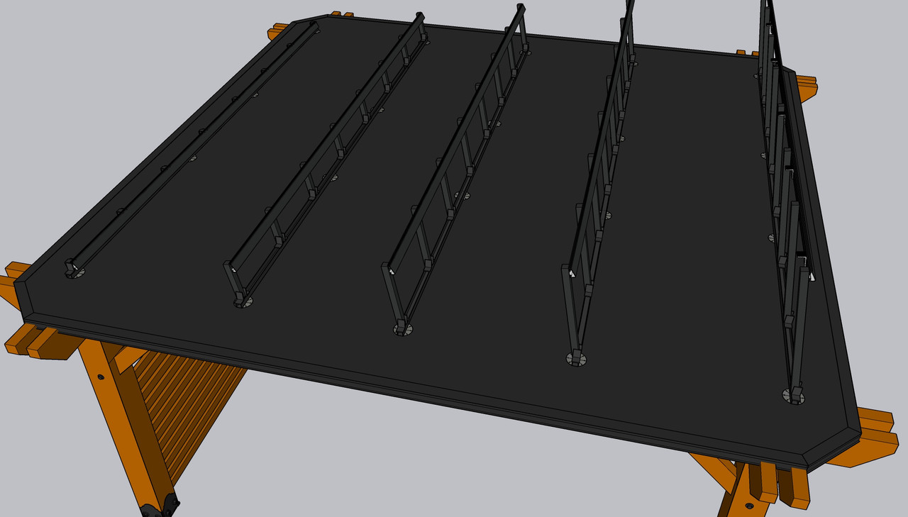
Then copying the design I found, eight telescoping legs per row seemed adequate for support struts. Each row of struts is secured with a rail at the top running parallel to the one at the bottom.
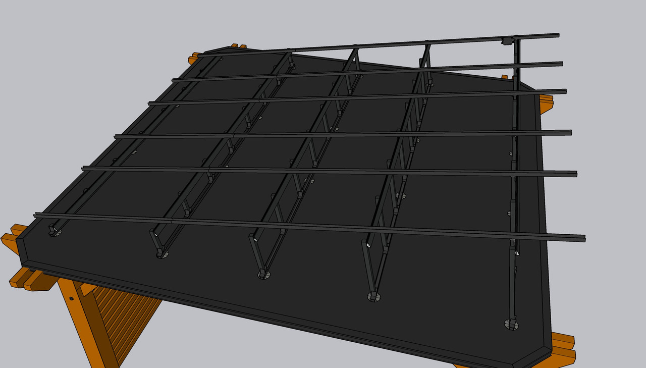
Finally six rails running perpendicular complete the framework.
My overkill brain says to bolt through the bottom of the top rail and then use an L-bracket to get two points of connection per rail at each intersection for added strength. I’ll have to have a long think as to whether there is any truth in this. The panels and microinverters are then secured to the top rails using standard hardware.
I started working on the lower rails yesterday. Not much progress was made but there was some. I only had about an hour of free time anyway with it being the Fourth of July. But the pics will be in the next Roof Redux post. Stay tuned.
