Solar Power Day 16
Concrete slabs are literally designed to come apart at the seams? Curious...
Today the solar crew returned at 9AM and with seven people in tow, so I knew a fair bit was going to be accomplished today. The big event I was looking forward to was the completion of the interconnection between the solar panels and my house mains. While there was still plenty of work left to complete, this was one of the final steps before firing up the system to test it.
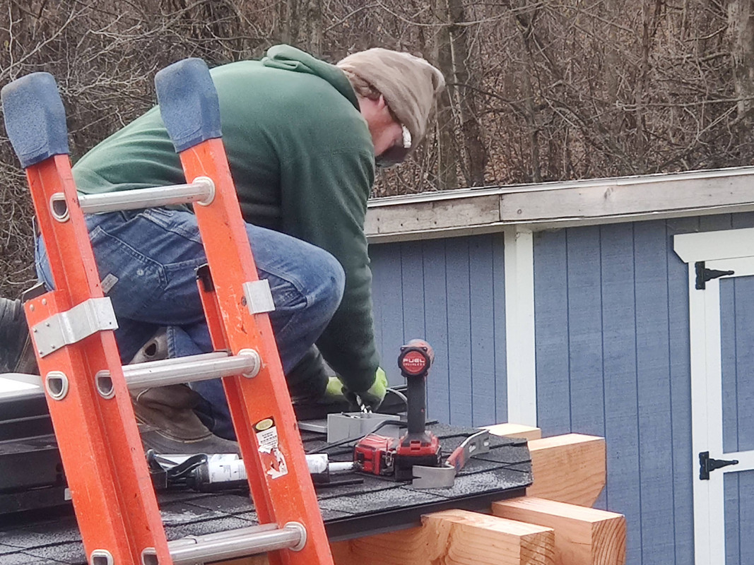
Like on several other days the crew split into two teams, with the electrician working on his own. The house roof team still had to swap the microinverters on the easternmost section of my roof to the correct ones, plus pull wires through the conduit running across my entire roof to the Enphase combiner on the west side of the house.
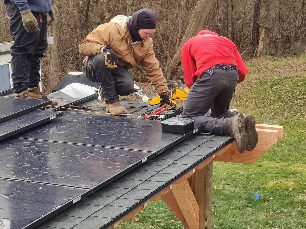
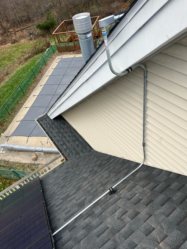 This cluster of panels is now ready to go
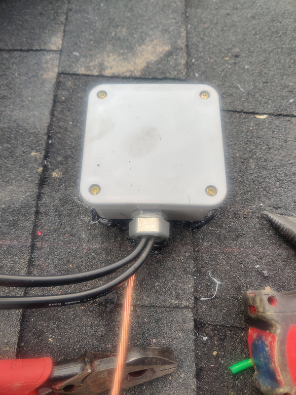
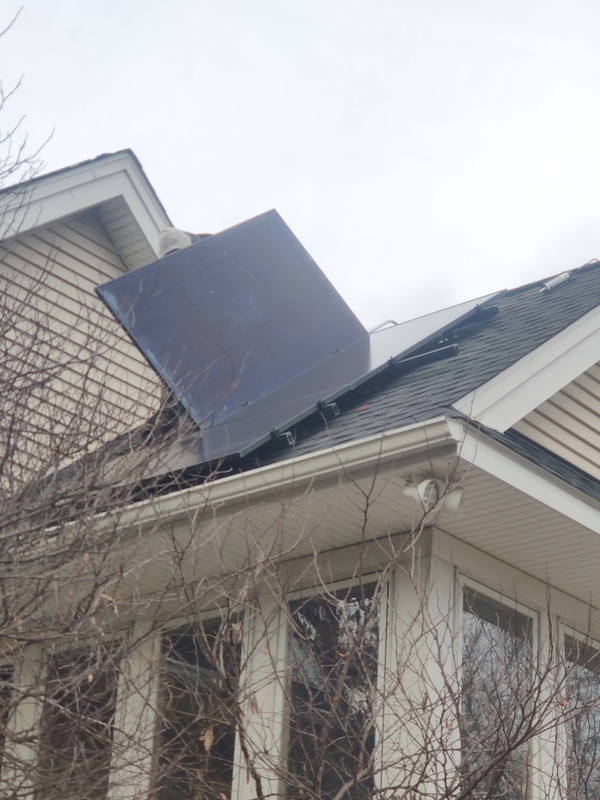
I also have an update to my last post about the last panel on the pergola. Turns out that there was a clearance issue with the junction box that prevented the panel from being secured for fear of cracking it. When the rails for the solar panels were mounted, instead of using metal feet like on normal roofs, the crew mounted the rails directly to the roof using lag screws going straight through the rail into the roof boards. This was done to minimize the amount of wind drag that could build up under the panels during a windstorm. No feet means a height loss of about two inches. Thankfully they old needed 1/8th of an inch, so they cut out just the top layer of shingles (the overlapping layer) and that was enough. They also caulked around the box to ensure no water would get underneath. But even if it did, the ice and water shield layer should protect the roof boards.
Once this was done the ground wire, which was deliberately left undone last week, was installed.
Once the last panel was secured to the pergola roof that part of the solar installation was complete.
Going back in time about two hours, while the pergola team was finishing up there, the electrician was working on the interconnection in my house’s disconnect box. It’s not often a house has this, but it did give us the advantage of having an existing box to work in without having to install another with a disconnect switch and junction box for the house mains.
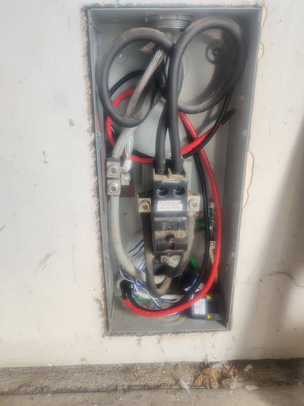
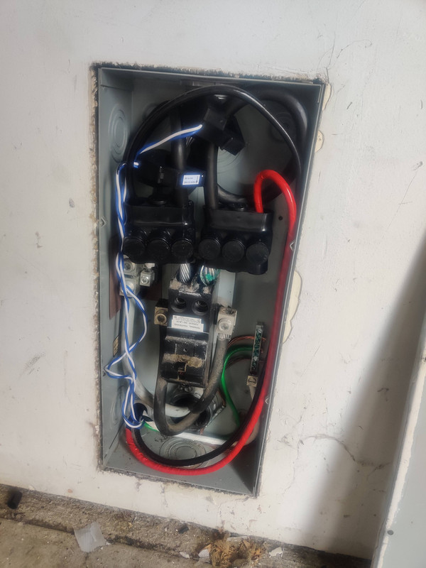
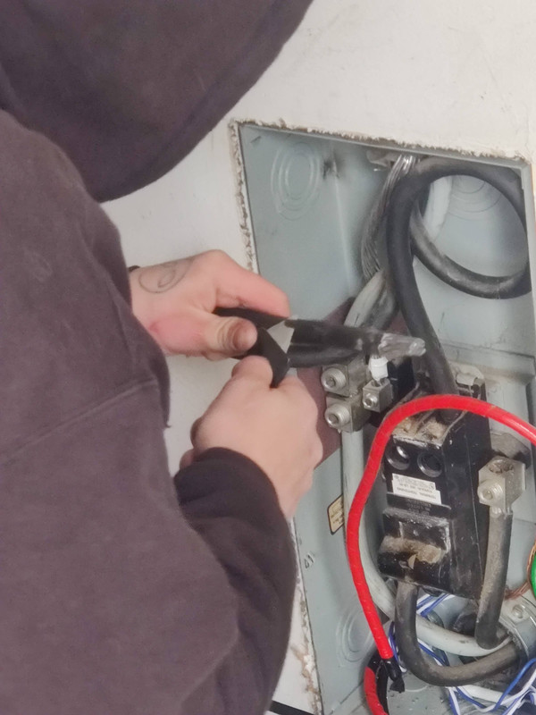
For reasons I can’t explain, the 200A breaker in this box is upside down. The two black wires on either side of the breaker come from my power meter while the two on top of it lead into the house. The gray wires on the left are the neutrals, again with the incoming power on the bottom and the wire on top leading to my main breaker panel. The red and black wires come from the Enphase IQ4 combiner, and the two black clamps in the bottom of the box are Enphase sensors for monitoring power usage.
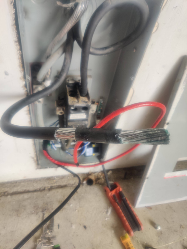
For anyone curious, like I was, I found out from the electrician that the reason for the loops is to leave extra wire in the box should the conductors be aluminum, which mine are. Since at the time of my house’s construction aluminum wiring was thought to corrode easily over time, the thinking was that leaving extra length inside the box and then cutting off an inch or so when the corrosion became a problem was something of a long-term solution. Well my house is roughly 25 years old and there’s no evidence of corrosion or other issues, so neither my electrician nor I have any reason to believe that I’ll encounter any corrosion within this house’s lifetime.
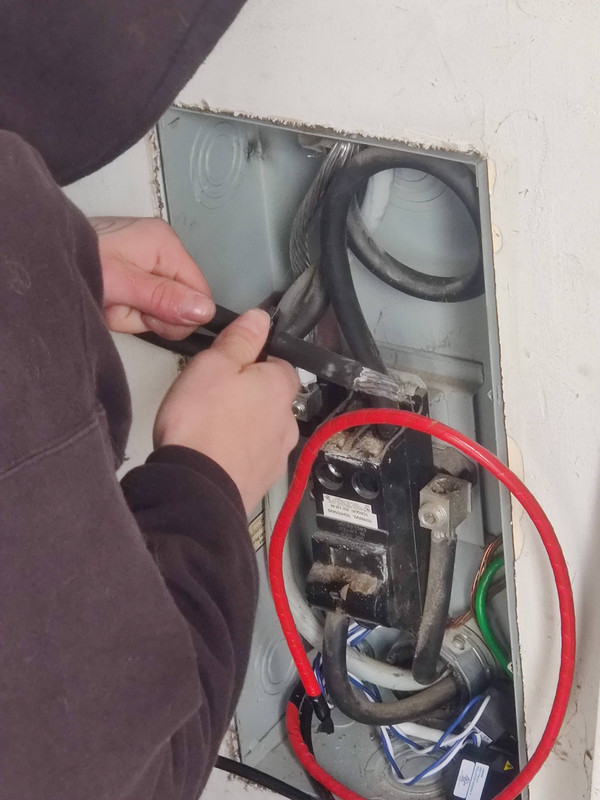
The electrician shut the power down at 10:10 and then disconnected one of the hot wires on the house side of the breaker. Using a utility knife he then cut away about an inch of insulation from the wire, leaving about two inches of insulation between the newly bared wire and the stripped end.
Next came the real struggle: forcing a gutter tap onto the wire past the two inches of insulation. Normally this wouldn’t have been too bad, but with the temperature outside being well below freezing, the insulation was rock solid.
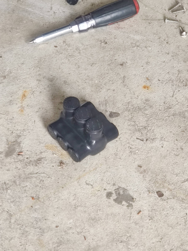 One of the gutter taps to be installed on the house mains. Each tap can connect up to three wires, secured by a covered screw.
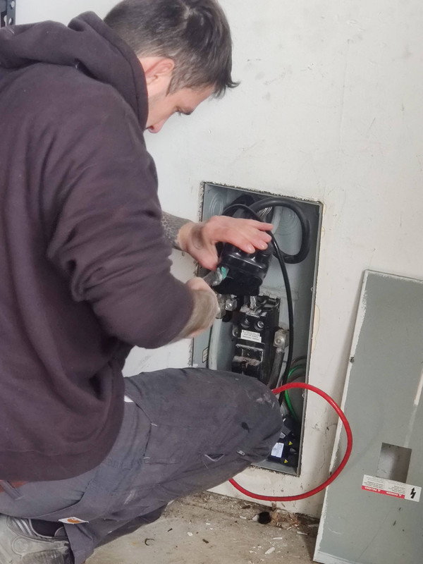 The solar electrician ended up using lineman pliers and twisting the wires to help pull them through the gutter tap
Because the power being output by the microinverters is 240VAC, only the hot wires needed to be tapped, not the neutral. This would only be needed if 120VAC were being produced, which doesn’t really make any sense since all homes in the US (that I’m aware of) are supplied with 240VAC in split phase, and only supplying power to one of the two hot wires would result in an uneven load in the main breaker panel.
Once both taps were complete the the mains were reinstalled into the breaker and the Enphase CT sensors clamped around the mains. A third sensor is pre-installed inside the combiner box and it works in tandem with these two sensors to determine how much power is being generated, imported (or exported) from the grid, and total consumption.
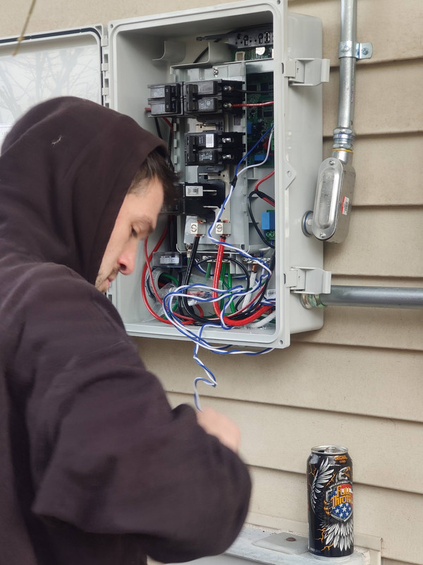 The electrician wiring up the CT sensors in the Enphase Combiner 4
Finally came the other hard part - putting the cover back on the disconnect box. With the box in my garage only being the disconnect breaker and not a full breaker panel (or load center to use the technical term) there was already very limited room to begin with, and installing a junction box between this and the power meter wasn’t possible since this box is right behind my power meter and slightly below it. It may not look it in the picture above, but those gutter taps actually protruded from the box about 1/8th of an inch, and because the wire loops ran behind the gutter taps, there was almost nowhere for them to go. The electrician obviously made it work in the end, but it was hardly free of struggle.
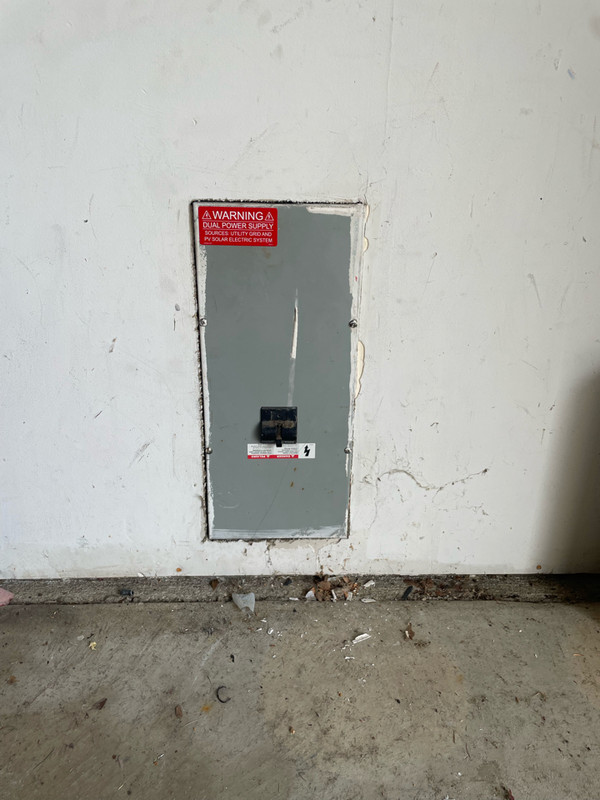 A PV warning label was added to this like all of the other boxes and conduits connected to my solar arrays
After an even hour power was restored to my house. The real time consumer in this process was forcing the gutter taps on. Had the insulation not been frozen stiff and able to flex and compress, the gutter taps probably would have taken only 15 minutes, not 45.
On a side note, this hour without power (hey that rhymes) reminded me that I really need to upgrade my server UPS batteries to Lithium Iron Phosphate (LiFePO4). The last time I had a sustained power outage the unit lasted around 45 minutes, but this time it didn’t even make it to 20 with the same load. Sealed lead acid batteries hate being discharged below 50% and that’s what happened seven months ago. This is the result of just letting them get that low.
 Only sixteen minutes? This thing doesn’t last very long … giggity…
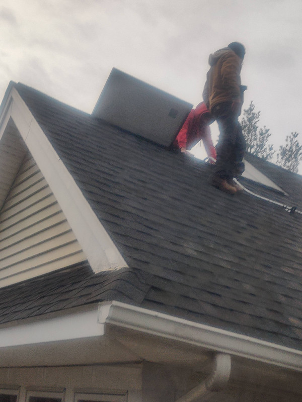
After power was restored and the pergola team finished their end, the team consolidated on the roof to address the latest surprise - one of the two lines coming from the roof arrays had too many panels connected to it and would be overloaded. In reality this likely would never happen, but to not address this would be a code violation and the system would fail inspection.
The first panels to be installed on my house were on the west roof, and the west side is also where all of the electrical connections are situated. At the time those panels and conduits were installed the house was only supposed to have 24 panels on it. Each 12-gauge Enphase q-cable is rated for 20 amps of current (like any other 12-gauge wire), or 13 microinverter connections. I’m not sure exactly what number they’re using to calculate that since running the math myself shows that each connection can supply up to 370W, well above the output rating of the microinverters we’re using, so maybe there’s a buffer they use when factoring this. Either way I’m not going to argue, they know the codes for solar installation way better than I do (which is to say I know next to nothing). But this meant that they had a lot more work to do on my house roof than originally planned. Not only would an existing line in the roof conduit have to be pulled out and replaced with larger gauge wire, the panel clusters had to be slightly regrouped electrically so as to satisfy the 13-panel maximum per line, and a third circuit needed to be added to the combiner box as a result.
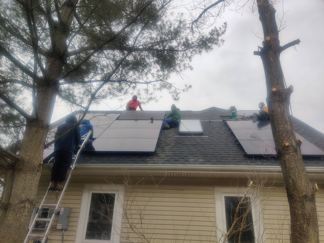 I felt bad for the crew at this point. Those panels had already each been pulled up once before to swap the microinverters. Now they had to do it again to fix the wiring.
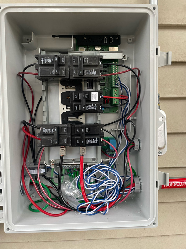 The combiner now has a fourth breaker for the incoming PV circuits
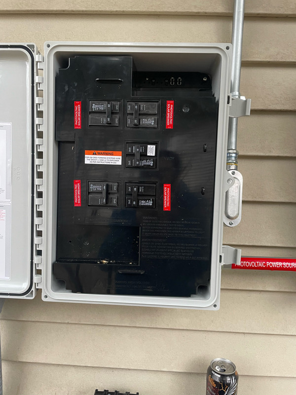 Completed combiner box all buttoned up
After all of this was done it got too dark for my phone to take decent pictures, but two of the crew stayed late to get the last of the panels mounted. Since I didn’t get a chance to speak with them before they departed for the evening I don’t know precisely what is left to do or whether the crew will be returning tomorrow or some other day. The electrician earlier today said he should be coming back, but, as has been evidenced multiple times throughout this project, plans can change. If he does come back his plans to are to do final system checks and then if those pass he will install the fuses in the solar disconnect next to the combiner, commission it, configure the combiner, and then order the full inspection to certify it. I’m told that by all rights once the inspection is complete that’s all that stands in my way from throwing the switch permanently and starting to produce power.
Phase 2 is nearing completion and one of my legitimate life goals is about to be achieved. As sappy as this will sound, a dream really is coming true. My next update, whenever that happens, should be the commissioning of the system. It’s looking like this is the final countdown. I can’t wait!

